
 '
'
PART LIST:
- 1 UV LED
- 1 LM117 (TO3)
- 1 RESISTOR 1ohm 2W
- 1 Piece of wood
- 1 Piece of Aluminium
- 1 Piece of plastic (transparent)
- 2 magnets
I wanted a smal one because i make prototypes one of a kind pcbs, and they are always small.
One wich could hold an arduino shield would be large enough.
Other projects i saw are using a large number of low power uv leds wich are in the miliwatt range. 80 Leds seems to be the minimum number to achieve 1W of UV radiated power, wich is what is needed to expose the PCB in a decent time.
This big number of leds needs a big PCB with a big number of holes and solder, and i don't like holes !

So i decided to use a single high power UV led.
The LED is 5W and is the higest power i could find at an affordable price.
It can output up to 1.5W of 400 nm UV radiation at 1500mA.
With high power leds, you should not mess with the current, moreover if you want to push it to the limits. If you go over 1.5A, it will bee VERY hot and its life much shorter than the expected 100.000 h. If you go below, you will have only a fraction of the expected output.
Never use a constant voltage driver, but use a constant curent one.
For this first test, i used a simple classic linear curent injector with a LM117.
This is the schematic of this simple regulation

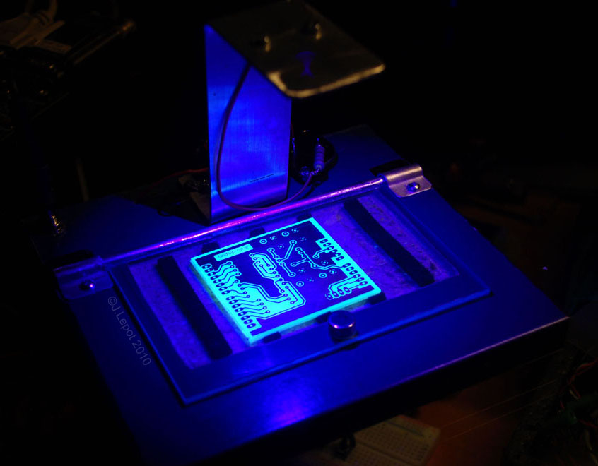
The "mechanical" part is also very simple.
I cut a wooden board 16 X 16 cm for the base, and in the center i made a recess to accommodate the PCB. I did fill this recess with foam slices to press the PCB against the cover when it is closed.
The cover is a 8 X 14 cm acrylic rectangle inserted in an aluminium tube which serves as a hinge.
A magnet is inserted in the base and another on is glued to the cover.

Support for the LED, which is also its heatsink, is made from a folded piece of aluminum. The LED is screwed at the top. The aluminium plate is the ground return, there is only one wire going to the led.
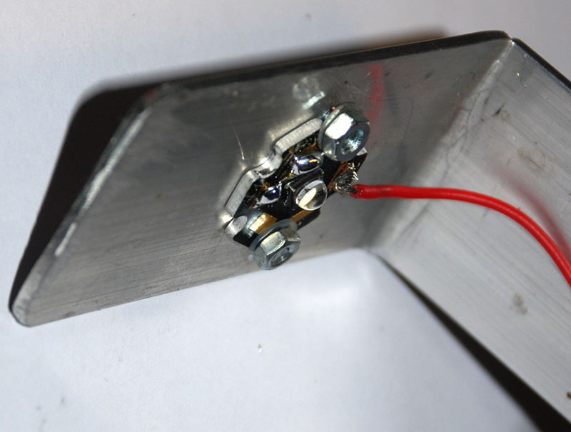
The LM117 is glued to the board upside down and the 1 ohm resistor is soldered directly on it.
A power switch is also glued on the base and a DC jack for the power supply.

This first "proof of concept" has no timer built in, but this will be added in the next release with the help of a Tiny45.
I was really positively surprised by the result.
I used simple laser printed transparent sheet and an exposure time of 2 min for the few tests i made.
First board is an arduino shield which has big traces and is easy, but the second one with 0.5mm pitch chip and 10 mils traces is a real test and was a 100% succes.


Thank you HackADay for posting this.
From the comments i read on HackAday, i must give some more details.
Of course, the UV light does not remove the copper !
I use Pre-Sensitised Copper-Clad Board.
After exposure i develop it (liquid NaOh diluted in water 1/10), about 1 min.

Next, i etch it with a 5/1 mix of HCL (chloridric acid) and H2O2 (oxygen peroxyd), 3 to 5 min.

